The construction and operation of a wind farm requires a large number of technical components that transport the generated electricity safely, reliably and economically into the grid. One of the most important – and often underestimated – components are medium-voltage cables. They form the backbone of the internal park cabling and ensure that each wind turbine conducts its electricity safely to the substation or grid connection point with low losses.
This guide explains in an understandable way:
Each wind turbine generates electrical energy at generator level (typically between 400 V and 1,000 V). This is transformed to medium voltage (usually 20 kV or 30 kV, more rarely 10 kV or 33 kV) via a transformer in the plant or tower.
The reason for using medium voltage:
- Lower transmission losses: Higher voltage = lower currents = less heat loss.
- Economical cable cross-sections: For medium voltage, smaller conductor cross-sections are sufficient than for low voltage, which reduces costs.
- Network compatibility: Grid connection points of the distribution system operators usually work in the medium-voltage range.
- Safe and robust parking structure: Medium-voltage cables are designed for the required transmission capacities and increase operational reliability.
In short: Without medium-voltage cables, the internal cabling of a wind farm would not be technically feasible.
Medium-voltage cables have several central tasks in the wind farm:
2.1 Power transmission from the wind turbine to the park grid
They connect:
- Wind turbines → collector wiring harness
- Collection cable harnesses → parking control center / transfer station
- Transfer station → substation / grid connection
2.2 Enabling ring or strand switching
Wind farms are typically referred to as:
- Ring system (higher reliability) or
- Strand system (more cost-effective)
wired. Medium-voltage cables must support suitable switching and protection concepts for this.
2.3 Communication and control
Many medium-voltage cables contain integrated fiber optic cables for :
- Plant communication
- Network control center connection
- Monitoring, securing and controlling
2.4 Grounding and equipotential bonding
The shielding braid of the cables adopts:
- Dissipation of residual currents
- Potential control
- Reduction of electromagnetic influences
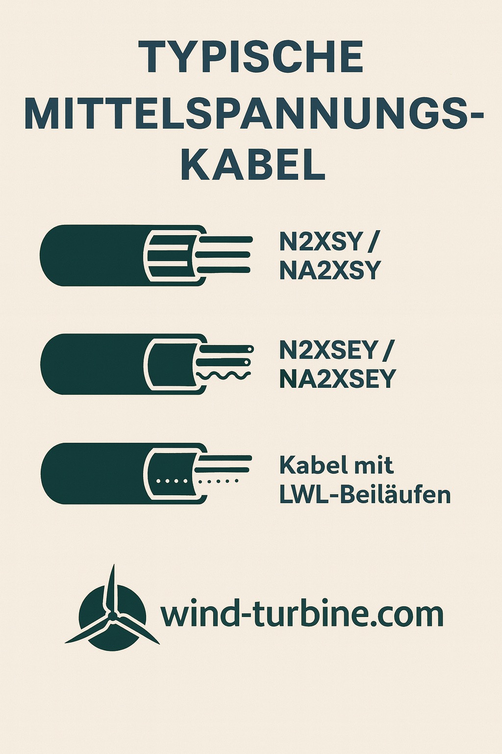
The most common medium-voltage cables in the wind farm are:
3.1 Cable Types
-
N2XSY / NA2XSY
Copper or aluminium conductors, XLPE insulation, widely used in the wind range (10–30 kV).
-
N2XSEY / NA2XSEY
With longitudinal and transverse tightness – useful for damp soils.
-
Cables with fiber optic lanes
Combined solution for energy + data.
3.2 Common voltage levels
- 20 kV (standard in Germany)
- 30 kV (growing importance for large parks)
- 33 kV (common for international projects)
3.3 Laying methods
- Direct burial
- Installation in the protective tube
- Cable trays (rare, mostly in the substation area)
- Underpasses (flush drilling method, HDD)
This is where the crucial part begins, because errors in cable planning are among the most costly problems in wind farm construction.
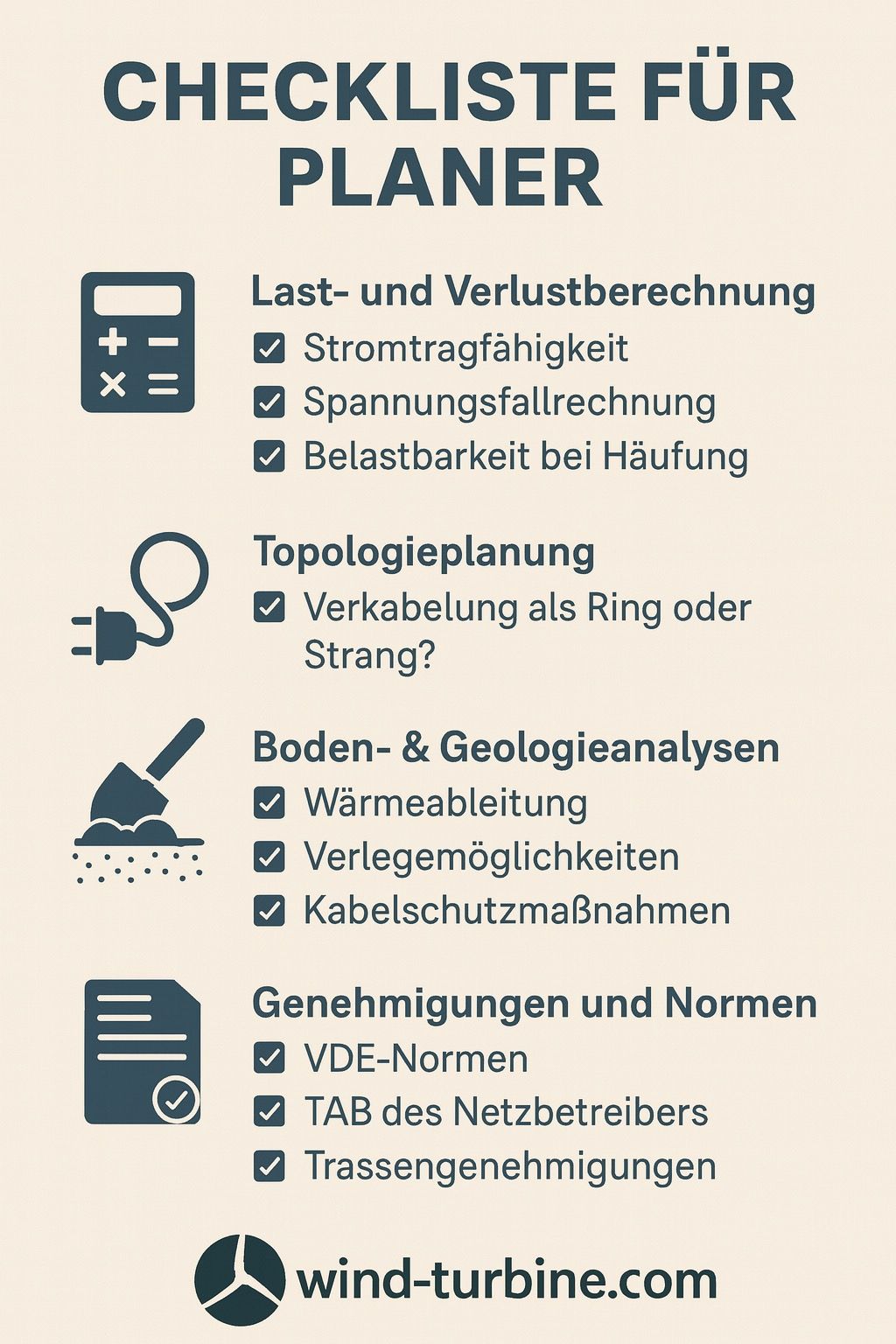
4.1 Load and Loss Calculation
Key aspects:
- Cable cross-section according to current carrying capacity
- Temperature-dependent load capacity
- Accumulation and parallel strands
- Voltage Maintenance and Voltage Drop Calculation
4.2 Topology Planning (Ring vs. Strand)
Ring wiring:
- Higher availability
-
In the event of cable damage, the park remains partially in operation
– Higher effort and higher costs
Strand cabling:
4.3 Soil & Geology Analyses
The soil affects:
- Heat dissipation
- Laying depth
- Protective measures
- Service life of the cable
Stony soil → sand bedding, protective pipes
Damp soil → longitudinally and transversely sealed cables useful
4.4 Mechanical stress
Particularly critical:
- Curve radii
- Tensile forces during laying
- Protection in transition areas (e.g. tower base)
4.5 EMC & Shielding Concepts
Important for:
- Measurement and control technology
- Minimization of interference
- Grounding concepts in the parking network
4.6 Permits and standards
Planners must take into account relevant standards, including:
- VDE 0276 (Medium Voltage Cable)
- VDE 0100 / 0101 (Construction of high-voltage systems)
- Technical connection conditions (TAB) of the network operator
- Building permits for routes, paths, underpasses
After commissioning, the long-term task begins: safe operation for 20-30 years.
5.1 Regular tests and measurements
Typical tests are:
- Partial discharge measurements
- Shell tests
- Insulation measurements
- Thermographic checks of joints and stations
5.2 Monitoring Critical Areas
Special danger zones:
- Socket points
- Transitions at the base of the tower
- Underpasses
- Areas with soil movement or agricultural use
5.3 Documentation & Path Tracking
Operators need to know where each cable is. Important for:
- Repairs
- Earthwork
- Incident management
Lack of documentation is one of the most common operational risks.
5.4 Typical error patterns
- Sheath damage caused by stones or tensile forces
- Socket defects (most common cause of failure)
- Moisture ingress
- Thermal overload
5.5 Repairs & Costs
Repairs of medium-voltage cables are time-consuming:
- Localization by fault location
- Uncovering the route
- Socket assembly under special conditions
Costs are often in the five-digit range per claim.
Medium-voltage cables are a central element of every wind farm. They ensure the safe, efficient and reliable transmission of the energy generated and have a significant impact on both construction and operating costs . Professional planning, high-quality installation and careful monitoring during operation are crucial for high turbine availability and trouble-free wind farm operation for decades.